
Mastercam Multiaxis Multi-Axis Flank Milling
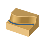
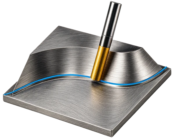
Flank milling is a multiaxis toolpath that uses the side of the tool instead of its tip to cut material. This enables highly efficient, high-quality machining, especially when machining long, thin, or curved surfaces. Also known as swarf milling, the method takes advantage of the tool’s entire cutting side, resulting in a consistent surface finish and reduced tool wear.
Flank milling is ideal for applications such as parting-off, finishing complex shapes, and especially roughing and finishing turbine blades, airfoils, and other aerodynamic components. The method is widely used in the aerospace and energy industries, but it is also suitable for many other manufacturing applications that require precision and a high-quality surface finish.
Mastercam provides a wide range of settings for flank milling, allowing users to control tool motion, axis tilting, transitions, and safety clearances. For example, users can define guide curves—the upper and lower profiles—control the behavior of the tool axis, and select different methods for synchronizing the toolpath. This makes the toolpath highly flexible and suitable for a wide variety of manufacturing needs.
Features
- Multiaxis motion: Machining is performed with five-axis motion, with the side of the tool following the selected geometry precisely. Tool-axis control can also be limited to four- or three-axis machining, providing greater flexibility for programming older machines.
- Geometry control: Users can select the geometry to be machined using guide curves—the upper and lower profiles. This allows the toolpath to be precisely limited to the desired surfaces and minimizes air cutting.
- Tool-axis control: Tool tilt can be defined in a variety of ways: automatically, according to the guide curves, using the shortest-distance principle, or by synchronizing different geometry curves. This makes it possible to control how the side of the tool contacts the surface and optimize chip flow.
- Methods: The toolpath can use several methods, including automatic (traditional), synchronization with ISO curves, or tilt lines. This provides flexibility for machining different parts and shapes.
- Cutting-direction control: Users can select the tool motion direction: left, right, inside, outside, front, or back. This ensures an optimal cutting sequence and surface finish based on the part geometry.
- Start-point settings: The toolpath start point can be defined in several ways: automatically, precisely, through a single point, using two points, or with a tilt line. This enables a safe and controlled start to machining.
- Holder checking and collision control: The toolpath includes comprehensive collision checking. The side of the tool can be checked against guide curves, machining geometry, or additional geometry. This helps prevent collisions in the holder, shank, and shoulder areas.
- Transitions and safety zones: Comprehensive settings are available for approach, retract, and transition movements, including tangent arcs, linear moves, and connecting splines. The tool can be returned to the safety zone in several ways, such as retracting to the feed distance, using rapid approaches, or following safety-distance splines. This minimizes air cutting and improves safety.
Applications
- Turbine blades and airfoil profiles: Flank milling is particularly well suited for manufacturing turbine and compressor blades, where long, curved, and tapered shapes require the side of the tool to ensure surface quality.
- Aerodynamic and hydrodynamic components: Aircraft wing components, propellers, impellers, and other flow-related components can be machined efficiently by using the side of the tool.
- Cutting thin walls free: The method is ideal for trimming components free, for example, when a component is separated from a billet along straight or curved lines.
- Mold and forming components: Complex mold surfaces can be finished using flank milling, resulting in consistent surface quality even across large contact areas.
- Energy and automotive industries: The method is suitable for parts requiring precise curved shapes, such as valve components, wind turbine parts, and demanding engine components.
Benefits
- Consistent surface quality: Using the side of the tool enables large surfaces to be machined with one consistent contact, reducing tool marks and improving visual quality.
- Extended tool life: Cutting forces are distributed over a larger area, reducing the load on the tool tip and extending tool life.
- Faster material removal: Flank milling enables efficient material removal across wide areas without requiring multiple overlapping passes.
- Flexibility across different axis configurations: Although this is a multiaxis method, users can force the toolpath to operate in a four- or three-axis environment, making it more versatile.
- Safety and collision control: Comprehensive collision checking and safety clearance settings improve process reliability, especially for complex geometries.
- Versatile transition options: Tangential arcs, lines, and various spline transitions allow the toolpath to conform optimally to the shape of the part.
Tips
- Extending the tool beyond the surface: If you want the tool to continue beyond the selected flank milling surface, enter a negative value under Tool control → Ending at on the Multiple cuts tab. This enables controlled tool movement beyond the surface without unnecessary stops.
- Optimal tool selection: Use cylindrical or tapered tools whose sides best match the shape of the surface. Ball-nose tools are suitable for flank milling only to a limited extent.
- Safety clearances: Set sufficient safety clearances for the holder, shank, and shoulder areas, especially when machining deep and complex shapes.
- Fine-tuning transitions: Select the approach and retract method that best suits the part. For example, a tangential arc produces smoother motion than a straight move.
- Using multiple passes: Use stepovers from top to bottom or bottom to top when you want to remove more material in a controlled manner or extend tool life.
- Simulating before cutting: Use Mastercam’s simulation features to verify that the toolpath follows the desired surfaces accurately and that collisions are avoided.
Summary
Mastercam Multiaxis Flank Milling is an advanced toolpath that uses the side of the tool to cut material from complex 3D geometries. It provides consistent surface quality, improves tool life, and enables efficient material removal, especially when machining turbines, airfoil profiles, molds, and other aerodynamic or hydrodynamic components.
Extensive settings, including the use of guide curves, tool-axis control, collision checking, and versatile transition options, make this method highly flexible. In addition, the ability to run the toolpath in five-, four-, or even three-axis mode improves usability across different machine configurations.
Flank milling is one of the most effective methods when surface quality, precision, and efficiency are required together—and it is an essential tool, particularly in high-demand manufacturing.


