Geometric Tolerances Location Symmetry
Symmetry is a location tolerance that defines how precisely a feature is positioned relative to a centerline or center plane. It indicates how evenly a feature is distributed in relation to a datum that serves as a reference. Symmetry ensures that a feature isn’t skewed or unbalanced with respect to the part’s center.
The tolerance zone consists of the space between two parallel zones placed around a centerline or center plane. The actual centerline of the feature must be located within this area, the size of which is determined by the tolerance specified in the drawing.
Applications
- Hole and shaft pairs: ensures that the hole is exactly symmetric relative to the outside surface.
- Structural parts: symmetry provides even load distribution, as in bearing housings or rotating components.
- Aesthetic and functional shapes: for example, the shapes of visible parts need to be symmetrical for appearance and assembly purposes.
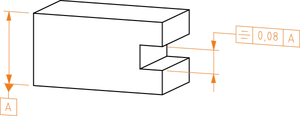
Notation and interpretation
The measured (actual) center plane must lie between two parallel planes that are 0.08 apart and are symmetrically located relative to datum A.
Definition of tolerance zone
The tolerance zone is limited by two parallel planes spaced t apart and symmetrically positioned with respect to the center (datum) plane.

Significance in manufacturing
Symmetry is especially important for parts where balance and even loading are essential. If features are not symmetrical, the result may be imbalance, vibration, uneven wear, or incorrect alignment of parts. However, demanding too tight a symmetry tolerance increases manufacturing costs and requires precise measurement, often with a coordinate measuring machine (CMM).
Symmetry tolerance according to ISO 1101 provides a clear way for designers and manufacturers to ensure that features are positioned symmetrically relative to a centerline or center plane.