Geometric Tolerances Orientation Angularity
Angularity is an orientation tolerance that specifies how precisely a feature—such as a surface, edge, or axis—is positioned at a given angle relative to a reference surface or axis. Unlike perpendicularity (90°) and parallelism (0°), angularity can be any angle specified by the designer. Angularity is classified as an orientation tolerance according to ISO 1101.
The tolerance zone is formed between two limiting surfaces set at the designed angle. All points of the inspected feature must lie between these surfaces. If an axis is involved, the tolerance zone forms a wedge-shaped area at the defined angle relative to the datum.
Applications
- Chamfers and sloped surfaces: Ensures the chamfer maintains its designed angle, for reasons such as assembly or strength.
- Machined grooves and guide surfaces: Angularity ensures that grooves and guides are accurately positioned relative to one another.
- Slanted connection points: For example, when a part needs to be installed at a specific angle and small deviations cannot impair function.
Symbol and Interpretation
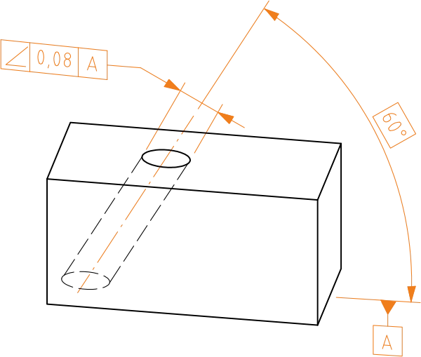
The measured (actual) centerline must lie within two parallel planes that are 0.08 units apart and set at a 60° (theoretically exact angle) relative to datum plane A.
Definition of the Tolerance Zone
The tolerance zone is limited by two parallel planes spaced t apart and set at the specified angle to the datum line.

Importance in Manufacturing
Angularity is a vital tolerance, especially in parts where precise angles affect assembly, sealing, or load distribution. If the angle deviates too much, parts may not fit together, loads can be misdirected, or movement may not be smooth. On the other hand, overly tight angularity requirements increase manufacturing costs, as they require extremely precise machining and measurement.
Angularity tolerance gives designers the flexibility to manage angular precision: accurate enough to guarantee function, but without unnecessary overengineering.