Geometric Tolerances Orientation Parallelism
Parallelism is an orientation tolerance that defines how accurately two surfaces, lines, or axes remain parallel to each other. It does not specify the distance between them, only the angular deviation relative to a reference surface or axis. Parallelism is one of the orientation tolerances presented in the ISO 1101 standard.
The tolerance zone is formed between two parallel surfaces or lines. All points on the measured feature must lie within this zone. If the feature is an axis, the tolerance zone is the space between two parallel cylindrical surfaces.
Applications
- Axes and holes: ensures the shaft runs parallel to the datum, which is important in rotating and sliding joints.
- Mating surfaces: for example, two surfaces that are mounted against each other on machines remain parallel, ensuring the load is evenly distributed.
- Guideways and tracks: parallelism prevents parts from sticking or wearing unevenly.
Symbol and Interpretation
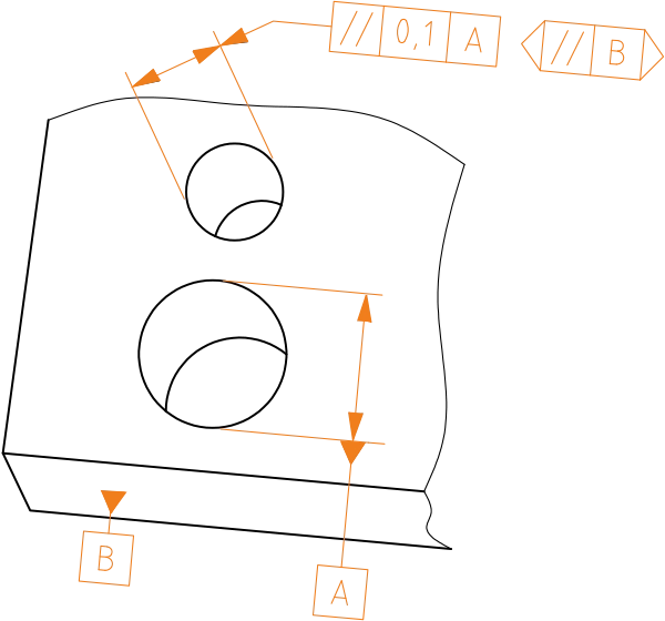
The measured (actual) center line must be between two parallel planes that are 0.1 apart and parallel to reference plane B.
Definition of Tolerance Zone
The tolerance zone is bounded by two parallel planes spaced t apart and parallel to the reference element.

Importance in Manufacturing
Parallelism is critical in many assemblies because misalignment can lead to excessive stresses, uneven wear, noise, or even complete failure of the joint. For example, machine guides must be precisely parallel to ensure smooth and consistent movement.
However, overly tight parallelism requirements increase manufacturing costs because they require precise machining and measurement. Therefore, the tolerance value should always be chosen based on the part’s function and application.